Bergen Community College Robotics Spring Internship 2017
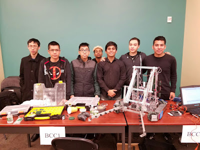
Initially, the old robotics team would like to welcome some of the new members into the team.


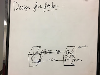
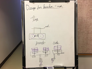
The BCC STEM Robotics Team is developing a ball launching robot using Autodesk Inventor for design purposes and Robot C for programming purposes. The team has developed 4 major concerns about the design for the robot. First, the robot must gather the balls that are laying on the ground. Second, the robot must feed these balls to an elevator. Third, the elevator must elevate the ball to the launcher. Fourth, the launcher must be able to have varying angles in which it can launch the balls. To account for all of these factors, the designing team had to draw some sketches and ideas on the board for different aspects for the robots as shown below.


OLD TEAM

NEW TEAM
(Members of the old team are only missing from the picture, not the team)

Oh and we missed tyler, so here he is......

New Members:
Deepa Banjara
Alexandra Cortez
Tyler Laursen-Carr


MONDAY (03/13/2017)
On Monday, a team member finished the construction of a small robot capable of omnidirectional movement. This was achieved with the use a specialized type of wheel called the Mecanum wheel. The wheel allows the robot to move in any direction which gives us a lot of advantage in the field. While testing the robot we found out that one of the wheels was not working because the wire connected to the high-speed motor was loose on the circuit board.
The purpose of this project was to test the NEW wheels before installing them into the main robot, once it is built. Here is one of the members diligently working on the project:


Once completed, the programming team set out to create a program that would make use of the specialized hardware. After some testing, the programming team realized that while the first program allowed for basic movement, it did not allow for full use of the robot's range of motion. Further testing was required by the programming team.
The purpose of this project was to test the NEW wheels before installing them into the main robot, once it is built. Here is one of the members diligently working on the project:


After completing the robot we tested it to confirm its compatibility with the Main Robot. The first few tests were mostly consistent with errors due to varying motors installed in the robot, wire glitches, and programming issues.
However, eventually the robot passed all the requirements for its functionality, and the project was concluded successfully.
The competition robot underwent some changes. Namely, a third motor was added to each side of the arm to give it a greater amount of torque. Since the design for the robot was so compact and precise, adding in new features proved to be a slight challenge as everything had to be put back the exact way it was built. After some struggle, the extra two motors were added. The building team would have to continue adding new features throughout the week in order to add slight improvements to the robot. Additionally, the programming team would have to modify the program to ensure it works with the new motors.
The robotics team’s primary goal is for the team to grow by teaching them new skills and providing them with an environment where these new skills can be applied. As such, the programming team decided to create a lesson plan to teach the other members the basics of programming and how it's applied to the hardware used in the Robotics Club. First, a basic set of bullet points was to be set up. While seemingly simple, the task proved to have its own set of challenges, such as how in depth the programmers wanted to go in terms of detail. With more details added to the lesson plan, the easier it would be to understand how several functions used in RobotC worked behind the scenes. However, by adding more details, the lesson would become much less beginner friendly, which defeats the purpose of the lesson. Additionally, the inclusion of great detail also meant the lesson would take a longer amount of time to get through. The programming team feels that programming is a skill that must be mastered through practice, and while traditional lessons are useful for conveying key concepts, practice is the best teacher. Given the limited teaching experience, the programming team has, the lesson guidelines require much greater discussion before the team is able to proceed to the next phase. The third revision of the key points to be discussed are listed below.
Fundamentals:
Important Notes to keep in mind, not listed in any particular order.
- RobotC is a text-based programming language based on the standard C programming language.
- An IDE stands for Integrated Development Environment. When one opens RobotC, all the tools needed to write a program. Components of an IDE include a text-editor, where all the code is written, and a compiler, which translates the code into machine language usable by the VEX Cortex.
- For the program to be usable, one must first type the program with the desired commands in the RobotC IDE and then compile the program. Once compiled, the code need only be downloaded to the robot.
- Before a program can be used, it must first, however, be created.
- The basics of RobotC must be understood so that the program can perform the desired operations. Proper programming conventions must also be understood to make the program readable by others. Readability of code is not necessary for it to be usable by the machine, but is useful in helping team members understand and use the code written by others.
- Generally speaking, the standard code follows three simple steps, Input, Processing, and Output. Data is input to the machine, the machine follows the instructions set by the programmer, and outputs the desired data, be it on screen or stored in a file.
- RobotC, being based on the C programming language, can also work with data, such as numbers and text. However, it is modified to allow easy control over external motors and sensors.
- Basic programs will be written within the “Task main()” function.
- All RobotC commands must end with a semicolon “;”.
- RobotC, like many other languages, is case-sensitive. This means that the names of any variables, functions, and motors are consistent throughout the program.
- Variables are essentially placeholders for data in a program. Variables come in different data types such as integer (int), floating point (float), and doubles (double). They can also hold text in the form of strings (string), and single characters (char). Another variable type is the boolean (bool), which holds the value of either TRUE or FALSE.
- Variables can be local, meaning they are only accessible in certain sections of the program, or global, meaning they can be used all throughout the program.
- Variables can have their values changed throughout the program, making them very useful in control or monitoring systems.
- When a programmer would like to use a specific data type but would like the value to remain unchanged throughout, a constant should be used. Like a variable, a constant can hold the value of many different data types, but its stored value cannot be changed by the program.
TUESDAY (03/14/2017)
Due to inclement weather, the team was unable to meet on Tuesday.
WEDNESDAY (03/15/2017)
The programming team met with the team members in charge of the small omnidirectional robot completed earlier in the week. The first program written for the small robot was based on the basic movement program used for the robot used for the competition robot. While both systems used similar forms of movement, the structure of the wheels required that the program run differently. After the repeated testing of the new program with the physical, it was revealed that the physical robot suffered from small hardware issues.


Newest Iteration of the Program
Once the building team completed most of the significant changes needed for the competitions robot's arm, the programming team was able to test the modified program to ensure that all of the arms components behaved as they should. The previous program made use of a potentiometer that monitored the arm's angular position. This allowed the program to determine just how far up or down the arm needed to move based on which button the operator pressed. However, since the arm was modified, the potentiometer had to be moved out of the way and has yet to be reinstalled. The programming team had to modify the current program just a bit so that the arm would respond to basic input from the VEX Joystick. The original control program is shown below followed by the modified program used for testing purposes.
Original Program

Modified Program

After completing the sketches and understand the design of the robot, the designing team commenced their journey through Autodesk Inventor to assemble our ideas together. In order to fit the balls in the elevator onto the top floor, we had to depend on the 3d printer due to lack of the required parts.

This half pipe tube was designed to fit all the constraints within the robot. The tube has been modified multiple times before the final product. The tube must fit the ball and the conveyor belt which will move the ball. Initially, the base of the tube was circular, however, that proved to be incompatible with the rectangular design of the base. A rectangular base was added to the tube. Next, the size of the base was too large to fit any parts from VEX. The base was diminished to a smaller size. Finally, the thickness of the tube may have caused an issue with the ball rolling inside of it. Therefore, the wall was chamfered into a small angle which looks like a ramp. This will allow the ball to roll without getting stuck outside the tube.

This image above shows the robot with 3 projects combined together that were developed by the team. However, this project is not complete because there is no model of the ball launcher yet.The main robot consists of a middle feeder that will allow the robot to collect multiple balls, and also do it as quickly as possible. The purpose of the robot is to collect balls and then launch it into a net. The tower in the back of the robot acts as an elevator for the robots, where they are taken to the second floor to be launched. The launcher is separately built to test the gear ratios, and the torque requirements, to achieve the furthest projection.

THURSDAY (03/16/2017)
The designing team has finally completed the base of the robot, along with the feed mechanism and the lifting mechanism. The robot has the capability to gather multiple balls while also lifting it to be launched at the net. The designing team was incredibly fortunate in the process. But the rectangular base did make it easier for the holes to match up and avoided and additional parts to be designed in order to connect the metal parts.
The second floor of the robot is still in progress but the actual launcher has been constructed, tested, and evaluated. The launcher needs more torque in order to launch at a greater distance, so the next step to updating the launcher is to change the gear ratio inside (the motor) or on the robot. The tests can be seen below:
Test #1: Experimenting the rotation of the balls, and also the stability.
Test #2: Testing the design on the field to measure the distance of the projection.
Test #3: Testing the design on the field with the net to determine the precision of the launcher towards a target.
After testing the launcher, we have concluded that the wheels need more torque and less speed. The team needs to find a balance between the two in order to achieve the furthest projection. Some of the factors that can change the distance of the projection are:
- Adding another motor to increase the stress endurance of the mechanism.
- Change the internal gears of the motors to transition from "Turbo Speed" (fastest) to "High speed" (second fastest).
- Using a 12/60 gear ratio instead of a 12/84 gear ratio in the external mechanism.
FRIDAY (03/17/2017)
The last day of the internship and the new robot is 50% finished through its progress to completion. Even though the construction of the robot will take up some time, the designing process probably helped decrease the amount of time it will take to construct because of the blueprints of the structure. We intend to follow the agenda for this robot, while simultaneously also improving the structures of the old robot.

Newest Robot

SIDE PROJECT:
On Thursday the programming team finalized the list of components to be used in a potential PC workstation build. The 'to be proposed' workstations were created by the programming team with the needs of the Robotics Club in mind, primarily the CAD designers. All aspects had to be considered, such as the CPU's clock speed, the number of CPU cores, and CPU cache as well as the other key components. While picking the additional parts, compatibility with the CPU and motherboard had to be kept in mind. Additionally, the workstation build would have to be capable enough to handle a powerful workstation GPU that would be used to handle advanced assemblies along with the animations and stress tests required to more accurately approve of designs before the building stage can proceed. Additional key concepts had to kept in mind, such as the "life span" of the components as well as the demands of the primary users. All of this had to be kept within a reasonable budget as well, adding further difficulty to the task. For example, a type of memory used in computers that handle sensitive information is ECC memory. ECC memory stands for Error Correcting Code memory and is used primarily in industries that require the most precise reproduction of data possible, such as the financial industry. While it would be useful to have, the price of ECC memory, as well as the relatively negligible benefits, meant that it would not make the final cut for the parts lists of absolutely necessary items. There was also much debate within the programming team as to which CPU would be most beneficial. Depending on the CAD program used, the greater amount of cores available would greater impact its performance. For example, such as with the use of SolidWorks, that specific CAD program would benefit from having cores with a much greater clock speed. In CPUs, the clock speed is generally divided between all the available cores. More cores mean the total clock speed is divided among a greater number of entities, lowering the clock speed of each individual core. This means that while each core can perform less task per second, more task per second is able to be performed simultaneously. Going back to the example with SolidWorks, having fewer cores, depending on the processor, would be of great help. However, for tasks such as rendering, a greater amount of cores would certainly speed up the process, saving time for the designers. Perhaps the second most important component of a workstation after the CPU would be the GPU. Whether or not a dedicated workstation card was needed was an issue under constant debate. It is no lie that a gaming GPU with the same physical components as a dedicated workstation GPU would be significantly cheaper, the issue lies with the drivers. Dedicated workstation GPUs have industry tested drivers that allow for more complex calculations to be handled by the computer as well as being able to provide more accurate results. The trade off being the cost and relative performance of the GPU. With all of this in mind, the final selection of parts was not an easy task and was thoroughly discussed within the team.
A total of four PC builds is to be considered and require feedback before they can be approved. Different models for each of the computers key components were eventually decided upon, however, given the nature of the task, the lists, as well as the price of components used, cannot be publicly disclosed at this time.
Tyler this is your sister Sam. We miss you and love you. Camden doesn't understand why you are ignoring his texts when you promised to write him. Please talk to him.
ReplyDelete